機電整合實務 Electromechanical Implementation
橋梁應變規運用
Application of Bridge Strain Gauges
Step 1: 構思與準備
評估橋樑維修提醒:測量平時橋樑所承受的力,倘若數值超過一定安全數值,就必須給予警示讓相關人員來檢查。
限制承載橋樑人數:藉由橋樑能承受的數值計算,限制橋上所能承受的人數。
Step 2: 材料準備
- 鋁條
- 砝碼
- 應變規 & HX711
- 伺服馬達 SG90
- LED 燈泡
- Arduino 控制板
- C 型夾
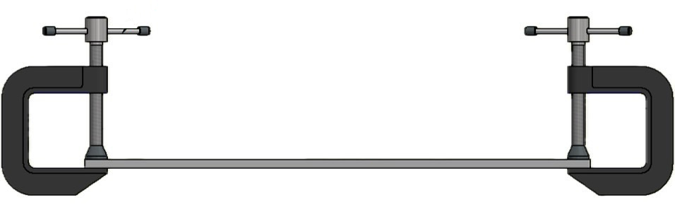
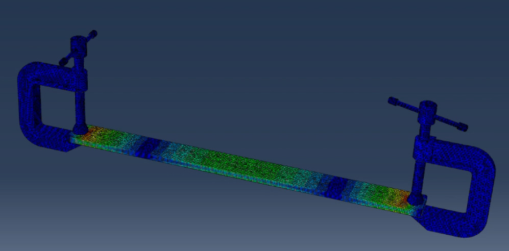
Step 3: 橋樑受力分析
使用有限元素分析軟體進行模擬,並擬定應變規黏貼位置。
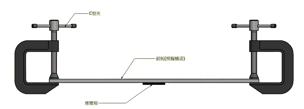
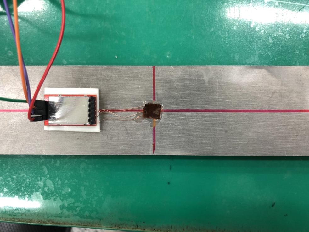
Step 4: 應變規位置與架設
應變規位置與架設示意圖:
Step 5: 柵欄運作電路圖
使用Tinkercad可以進行模擬真實運作情況,進一步確認自己的程式碼是否有問題。
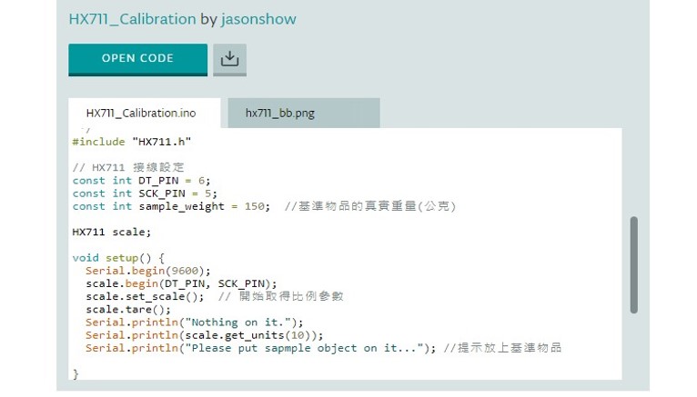
Step 6: 感測器編譯與校正
感測器與量測器相同在使用前必須先進行校正。
程式碼:
#include "HX711.h"
#include
// 接線設定
const int DT_PIN = 6;
const int SCK_PIN = 5;
Servo myServo1;
Servo myServo2;
int pos = 0; // 設定初始位置
const int scale_factor = 350; // 比例參數
HX711 scale;

void setup() {
    Serial.begin(9600);
    Serial.println("Initializing the scale");
    scale.begin(DT_PIN, SCK_PIN);

    Serial.println("Before setting up the scale:");
    Serial.println(scale.get_units(5), 0); // 未設定比例參數前的數值
    scale.set_scale(scale_factor); // 設定比例參數
    scale.tare(); // 歸零

    Serial.println("After setting up the scale:");
    Serial.println(scale.get_units(5), 0); // 設定比例參數後的數值
    Serial.println("Readings:");
    pinMode(LED_BUILTIN, OUTPUT);
    myServo1.attach(9);
    myServo2.attach(10);
}

void loop() {
    Serial.print(scale.get_units(1), 0); Serial.println("\t");
    delay(1000);
    if (scale.get_units(1) < -500) {
        digitalWrite(LED_BUILTIN, HIGH);
        delay(2000);
        myServo1.write(90);
        myServo2.write(90);
    } else {
        digitalWrite(LED_BUILTIN, LOW);
        delay(2000);
        myServo1.write(0);
        myServo2.write(0);
    }

    delay(10);
    scale.power_down(); // 進入睡眠模式
    delay(10);
    scale.power_up(); // 結束睡眠模式
}
HX711程式碼校正:
Step 7: 負荷結果展示
對於模擬的橋樑施加負荷,並檢測應變規的數值變化。
數值紀錄:

Step 8: 柵欄運作展示
Step 9: 柵欄負荷過載警示
程式碼:
#include "HX711.h"
#include

// 接線設定
const int DT_PIN = 6;
const int SCK_PIN = 5;
Servo myServo1;
Servo myServo2;

int pos = 0;  // 設定舵機位置

const int scale_factor = 350;  // 比例參數,依據校正程式中取得
HX711 scale;

void setup() {
  Serial.begin(9600);
  Serial.println("Initializing the scale");

  scale.begin(DT_PIN, SCK_PIN);

  Serial.println("Before setting up the scale:");
  Serial.println(scale.get_units(5), 0);  // 沒設定比例參數的數值

  scale.set_scale(scale_factor);  // 設定比例參數
  scale.tare();  // 歸零


  Serial.println("After setting up the scale:");
  Serial.println(scale.get_units(5), 0);  // 設定比例參數後的數值

  Serial.println("Readings:");
  pinMode(LED_BUILTIN, OUTPUT);  // 在這個訊息之前就不要放東西在電子稱上
  myServo1.attach(9);
  myServo2.attach(10);
}
void loop() {
  Serial.print(scale.get_units(1), 0);
  Serial.println("\t");
  delay(1000);

  if (scale.get_units(1) > -500) {
    digitalWrite(LED_BUILTIN, LOW);
    Serial.println(1);
    delay(2000);
    myServo1.write(0);
    myServo2.write(0);
  }
  else if (scale.get_units(1) < -1000) {
    digitalWrite(LED_BUILTIN, LOW);
    Serial.println(3);
    delayMicroseconds(100000);
    digitalWrite(LED_BUILTIN, HIGH);
    delayMicroseconds(100000);
  }
  else if (scale.get_units(1) < -500) {
    digitalWrite(LED_BUILTIN, HIGH);
    Serial.println(2);
    delay(2000);
    myServo1.write(90);
    myServo2.write(90);
  }

  delay(10);
  scale.power_down();  // 進入睡眠模式
  delay(10);
  scale.power_up();  // 結束睡眠模式
}